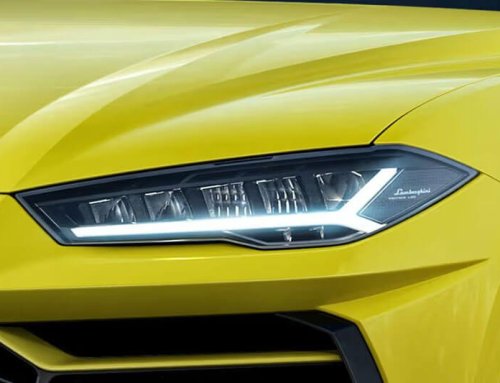
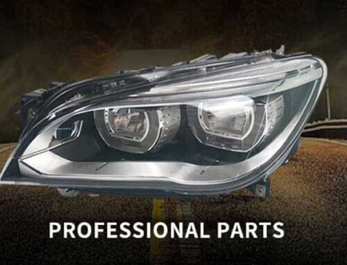
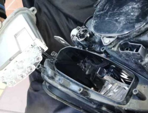
In simple terms, “PCB thermal separation” means consciously separating the heat-generating areas from the areas carrying circuitry/signals in the PCB design structure to prevent heat from directly affecting sensitive circuits.
I. What does thermal separation mean?
In certain products (especially automotive lights, LED light boards, power boards, and power driver boards), two completely different requirements arise:
The circuit needs to operate stably and should not be affected by high temperatures.
Power devices (LEDs, MOSFETs, driver chips) generate a lot of heat and need to dissipate it quickly.
“Electrical-thermal separation” addresses these two requirements by designing the PCB structure as follows:
Heat-generating modules (hot zones) → Separate placement / Separate copper foil / Separate metal plate for heat conduction
Circuit control areas (electrical zones) → Isolated from hot zones to prevent heat transfer.
Sometimes this is done using:
Double-layer board with the hot zone cutout
Metal substrate (MCPCB) + FR4 control board
Hot zones and electrical zones are isolated with insulating material.
In short: Heat is heat, and electricity is electricity; heat should not affect electricity.

II. Why do we need electrical-thermal separation? What is its purpose?
1. Reduce temperature and improve reliability
The lifespan of electronic components is inversely proportional to temperature.
For example, for every 10°C increase in LED junction temperature, lifespan can decrease by 30%–50%.
Isolating the heatsink can:
Fastly conduct heat to the metal base plate/heat sink
Prevent heat from being conducted to ICs, driver chips, and capacitors
Suitable for your common automotive lighting products.
2. Prevent circuit performance drift/damage
Many components (such as electrolytic capacitors, MCUs, and resistors) cannot operate at high temperatures for extended periods.
Electrothermal separation keeps these sensitive components cooler, ensuring:
Stable driver output
Flicker-free light
No over-temperature protection/system crashes
3. Increased power handling capacity
With an isolated heatsink, you can boldly:
Increase copper thickness (2oz, 3oz)
Directly connect to metal heat sinks
Use more thermal vias
Increase heat dissipation area
Brighter, higher wattage, and longer lifespan.
4. Simplified Heat Dissipation Design
For example, LED lights are typically designed like this:
MCPCB (Metal-on-PCB) – responsible for heat dissipation
FR4 small control board – responsible for circuit stability
Separating heat and electricity makes the heat dissipation structure clearer and more reliable.
III. Why is heat and electricity separation especially necessary in automotive lights?
LEDs themselves generate a lot of heat (chip junction temperature upper limit 150°C).
If the LED and driver are on the same FR4 board:
FR4 has poor thermal conductivity, and the driver chip will be damaged by the LED.
The LED junction temperature is too high → light decay, yellowing, and reduced lifespan.
Therefore, automotive daytime running lights and high/low beam headlights typically use:
Metal-on-PCB for the LED hot zone
FR4 board for power supply, control, and CAN chip
This is a typical “heat and electricity separation structure”.

IV. In short (very simple):
PCB heat and electricity separation separates the heat-generating and electrical components, allowing heat to dissipate quickly, making the circuit more stable and the light more durable.